If you own a 3D printer and have used it at least once, you are probably aware of the importance of the layer fan. The proper configuration of this little component will make or break the outcome of your print. Needless to say, it is necessary to have a working layer fan ready to be used when required.
If you are currently having issues with your layer fan, you’ve come to the right place. I’ll guide you step by step through the most common causes that lead to this problem and we’ll easily solve it. So, why is the layer not working on your 3d printer?
The layer fan of a 3D printer may not be working due to the printing parameters of the Slicer, the machine configuration, a hardware issue, or because an external object, such as filament, is blocking the fan, not allowing it to move. It can be solved by making sure that all layer-fan-related settings are enabled inside of the slicer.
Reasons why the cooling fan might not be working

As I stated above, there are a few reasons that can lead us to have a non-working layer fan! As always, I’ll first go through the causes that are the most probable and easy to fix and leave the most difficult for later stages in order to minimize our effort in solving this issue. Let’s get started!
Cooling Fan not working due to settings in Slicer
Sometimes, the problem is not with the cooler fan itself, but with the parameters set in the slicer. One of the slicer’s most important functions is the rotation speed of the fan. With this parameter, we can make the fan turn off in certain layers, or turn it on at a certain height of the print.
Before continuing, check if there is an option in your slicer to enable/disable the layer fan and turn it on / off (something similar to “allow cooling” or “enable cooling fans”). Some materials, such as TPU, do not need cooling (it can even be harmful). With this option, we quickly disable this feature and re-enable it when we use filaments that need cooling (such as PLA). It may very well be the case that you printed an object with a thermoplastic that requires the fan to be turned off, and forgot to revert it back!
If the fan still doesn’t work, let’s check the slicing parameters.
The basic cooling parameters are:
Fan full at height
This allows you to set the height of the object you want the fan to reach its maximum speed. During the printing of the lower layers, the layer fan will run at a slower speed, starting from 0 on the first layer. As the z-axis rises, the slicer will command the layer fan to increase its speed in a linear proportion until it reaches 100% at the set height. If the fan is off on the first layer, wait for that layer to finish to verify that it turns on afterward.
Another characteristic of the most common fans is that they need a minimum voltage to start spinning, so they may not spin at all in layers where the speed is set below this minimum voltage. The control boards use PWM (pulse-width modulation) to vary the voltage that the fan receives, but they do not receive information about its actual rotation speed. This way, you see on the printer’s screen that the fan is receiving the signal to move, but the fan remains stationary.
To eliminate this problem, you can set a lower height in “Fan full at height”, so that the voltage is divided into larger amounts. A recommended value is 0.4mm, which ensures good adhesion in the first layers.
Regular/maximum fan speed
None of these settings should be 0, or the fan won’t work. Set regular speed to 80% and maximum speed to 100%.
Regular/maximum fan speed threshold
With this parameter, you can define the layer time that causes the fan to switch from its maximum speed to its regular speed. Check that the values are in the correct range (from 5 to 30 seconds).
For a quick test of fan operation, print a piece with cooling enabled and “Fan full at height” set to 0. The fan should turn on when you start printing.
Cooling Fan not working due to G-Code

What is G-Code in 3d printing?
G-code is the programming language used for numerical control (CNC). Its use is widely spread in machine tools such as milling machines, lathes, and 3d printers.
It is made up of code lines that “tell” the machine what to do and how to do it. Each line is an instruction that indicates displacement, speed, and trajectory, among other things. In 3d printers, also has instructions for temperature changes or voltage variation in the fans.
Although it is not necessary to know the syntax of this code to use a 3d printer (the slicer software takes care of that), it is convenient to know some commands to verify that our printer is receiving the order that we want it to fulfill.
Possible causes in the G-Code
The command used in 3d printing to turn on the layer fan is M106. To turn it off, use M107. We are going to verify that the code is applied to the main extruder (normally, it is identified with the number 0). Open any model in your slicer and slice it using your normal settings. Then, save the generated G-code file and open it with any text editor (like notepad or notepad++). Search the code for the command “M106”. The syntax of the code should be this:
“M106 P0 S255”
- “M106” turns on the fan.
- “P0” indicates that the fan is associated with extruder 0. By default, it is the main extruder. If you only have one extruder installed, check that this value corresponds to the one set on your control board and modify it if necessary. If you are using two extruders, check that the wiring is in its correct position.
- “S255” controls the width of the PWM pulse that is sent to the fan. 0 is off, and 255 is 100% speed. Remember that some fans need a minimum value to start spinning. Until you find the fault, set this value to 255 for all tests.
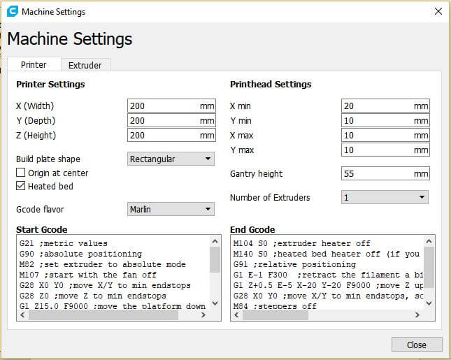
Make sure that the machine configuration on your slicer also refers to that fan as P0 or “Fan 0”. It is not uncommon that the problem is caused due to the fan being referred to as P1 or Fan 1 in the slicer. In Ultimaker’s Cura, you can check this by going to:
Settings -> Printer -> Manage Printers -> select your printer and click on “Machine Settings” -> Extruder 1 (or 2) -> Cooling Fan Number
Cooling fan not working due to hardware issues
If you still haven’t found the problem in your layer fans, it’s time to check the hardware. Let’s go through the most common issues that can lead to your layer fan not working properly!
The cooling fan is broken
The fan could be overloaded by a voltage peak, or it has simply exhausted its useful life. The only solution is to replace it with a new one. Verify that the fan’s operating voltage is the same as the one supplied by the control board. Also make sure not to exceed the current consumption that the board supports. If these values are not correct, you could burn out the new fan or even destroy the control board.
The control board does not deliver the required current / voltage
This may be due to faults in the electronics of the 3d printer. You can verify this using a multimeter or by placing another fan (that you know it works properly) on the layer fan jack. If you want to make sure that your layer fan is broken, take a look at the following video!
Although it is refered to as a computer fan, the same principles apply to our present problem!
The connection pins are loose or not making contact
This is a very common mistake since the control boards and the connection tabs can be different when they were not manufactured by the same manufacturer. Try swapping the fan plug for one that plugs firmly into the board.
The fan cables are cut
Since the fan cables carry a small amount of electric current, they are made up of very few copper wires. With the movement of the printer, these can be cut. If you can’t find any cut wire, you will need a multimeter to check this problem.
The welds on the fan plate are faulty
If the soldering was not done correctly, the connection may fail. Check the welds on the fan plate. To access the plate, peel off the label on the back of the fan. Look for defects in the solder, loose wires, or excess tin. If you know how to solder with tin, fixing this problem is very easy.
Cooling fan is stuck
Sometimes, small particles get stuck inside the fans. If you use hairspray to improve bed adhesion, cover your fans before spraying it, as it sticks everywhere, including your fan’s paddles.
Checking the cooling fan wiring with a multimeter
To check the wiring of our 3d printer we are going to use two functions of the multimeter:
- Continuity check
- Tension (voltage) measurement
Checking the condition of the cables: Before getting started, verify that the black lead from the multimeter is inserted into the COM Jack and the red lead into the VΩ Jack.
Select Continuity by turning the multimeter’s selector wheel. With the circuit de-energized, place the test leads on both ends of the cable being tested. If the cable is in a good condition, the multimeter will beep. If you don’t hear any beep, the cable is cut at some point and needs to be replaced. Check every wire from the power source to the control board.
Also, check the continuity between the connector and the fan’s board. Repeat the procedure for all terminals. If any of them is cut, the fan won’t work.
You can also verify that the control board is delivering the necessary voltage on its pins. To do this, turn the selector wheel of the multimeter to the position “20V” for direct current. Place the black test lead on any pin identified as GND. Connect the red test lead to the positive pin on the board. The multimeter display should indicate 12V (or the working voltage of your fan). Remember to do this test with the printer turned on and at a time when the layer fan is supposed to be working.
Recommended cooling fan settings for 3D printing
So, now that we (supposedly) fixed the issue with your layer fan, let’s go a step further and optimize the settings for each type of thermoplastic! I recommend you to set the following cooling values for the following materials:
Layer Fan for PLA:
- Cooling enabled: YES
- Layer fan Speed: 100% (except for the first layer to improve adhesion)
ABS:
- Cooling enabled: NOT RECOMMENDED. Cooling might generate warping or cracking.
- Layer fan Speed: below 40% if strictly needed (for printing bridges or overhangs)
PETG:
- Cooling enabled: NOT RECOMMENDED.
- Layer fan Speed: 30% (It may cause bad layer adhesion. If that happens, try disabling cooling)
TPU:
- Cooling enabled: NO
- Layer fan Speed: 0% (using slow printing speeds gives the layer enough cooling time)
Feel free to increase/decrease these values, since different fans may have more or less blowing power.
Conclusion
By now, I hope that you have a fully working fan under your control. If you’re still having issues, please leave a comment and I’ll try to assist you in fixing the issue. It is always a great opportunity to learn new things and keep this article updated!
Check out our recommended products section

We created a recommended products section that will allow you to remove the guesswork and reduce the time spent researching what printer, filament, or upgrades to get, since we know that this can be a very daunting task and which generally leads to a lot of confusion.
We have selected just a handful of 3D printers that we consider to be good for beginners as well as intermediates, and even experts, making the decision easier, and the filaments, as well as the upgrades listed, were all tested by us and carefully selected, so you know that whichever one you choose will work as intended.
Error processing API data.

How does the PWM signal produced by a 3D printer to control a 2 or 3 pin fan differ from the PWM signal that a PC produces to control a 4 pin fan?
If they are the same it should be possible to connect a 4 pin fan to a 3D printer as follows….
1=0, 2=12V, 3=NC, 4=3D printer part fan output.
That might improve the fans ability to start at low speed? I’m guessing they are too different for this to work.