When we get started in the 3d printing world, we first learn about the reverse relationship between the output quality of a piece and the movement speed of the printer. By this, I mean none other than the simple fact that a lower movement speed of the extruding will generally yield better looking object.
As time goes by, we also learn about more parameters that can be tweaked in order to get the desired result for our specific purposes. Two important settings related to movement speed are jerk and acceleration. Although they are more subtle and not as straightforward, they are surprinsignly important, and can make or break our project.
Jerk will determines the speed range (from 0mm/s to the specified velocity) in which the printer will completely ignore the acceleration parameter and go straight to the speed defined under the jerk setting. Acceleration, on the other hand, determines the rate of change of the movement speed with respect to time. This rate of change is defined in mm/s and affects the printing speed until reaching the maximum movement velocity.
Defining Jerking and Acceleration in 3d printing
3d printers use a very powerful control board in terms of calculation capabilities. With this board, the G-code (stored on an SD card or sent by means of a USB cable) can be interpreted and executed. This code gives information about direction and speed of movement, which is read and executed line by line by our printer. However, there are values established in the machine’s firmware that are not written in the G-code, which define in more detail how the movements are executed.
Among them, we can mention jerk and acceleration, which are important to achieve proper dimensional accuracy in an acceptable printing time
Somehow ironically, jerk tends to confuse those folks that have a more technical background. This is due to the fact that this term is defined in physics, but has another meaning when dealing with 3d printers. Ignorant people like myself don’t have to deal with this confusion since I did not know of this ambiguity before doing the proper research for this article.
In case you are intrigued, in physics, we can define acceleration as the rate of change of the velocity with respect to time. Analogously, jerk is none other than the rate of change of acceleration with respect to time. Mathematically, they are the first and second derivatives of velocity with respect to time.
Having clarified this (un)necesary distinction, lets define jerk and acceleration for 3d printing!
What is jerking in 3d printing?
Jerk is a parameter that measures the minimum speed variation that requires acceleration on one axis. Although it sounds complex, it can be seen more easily when the speed variation occurs in a corner: when reaching the extreme, the extruder must “brake” before changing direction. If the jerk value is too low, the movement will be smoother when it reaches the corner and the speed variation will not be drastic when the hotend changes direction.
For example, if we set print jerk to 20mm/s, we are telling the printer to go instantaneously from 0mm/s to 20mm/s ignoring the acceleration parameter. Acceleration will only affect further increases in velocity from 20mm/s to the maximum speed.
Otherwise, if the jerk value is set too high, it will take less time to reach the maximum speed and then it will reduce printing times. Like all parameters in 3d printing, a point of balance must be found between speed and print quality, since increasing this value too much increases vibrations and generates issues such as ghosting or loss of steps in the motor.
What is acceleration in 3d printing?
Acceleration indicates how fast the speed of motion increases on each axis. Like when driving a car, maximum speed is only reached when you have enough distance. By definition, the printer runs at a speed between 0mm/s (completely still) and the maximum speed set on the slicer, especially on complex parts with many corners.
Increasing the acceleration makes the printer faster if it has enough distance to travel. Jerk is responsible for the instantaneous speed increases. Together, they can smooth your printer while reducing print time.
Although you can set different acceleration and jerk values for each axis, it is recommended to use the same values on the X-axis and on the Y-axis. This way, printed objects will look the same, no matter how they were oriented during printing.
How does Jerking and Acceleration impact on overall quality?
When the extruder changes direction (or speed), it must first reduce the speed on one axis and increase speed on another. If the jerk is set too high, this change will be quick and abrupt, which can cause unwanted vibration to be transmitted to the part. Likewise, if the set acceleration is too high, the printer may not have enough distance or time to stop the hotend carriage. This produces an overshoot that takes the hotend beyond the desired position.
In contrast, setting low jerk and acceleration values leads our printer to work in a conservative range of motion. Finishes may be better, but printing will take more time and make it unfeasible in economic terms. As a general rule, we’ll thrive for the highest points of jerk and acceleration at which the looks of the object remains acceptable.
Consequences of jerk settings on printing quality
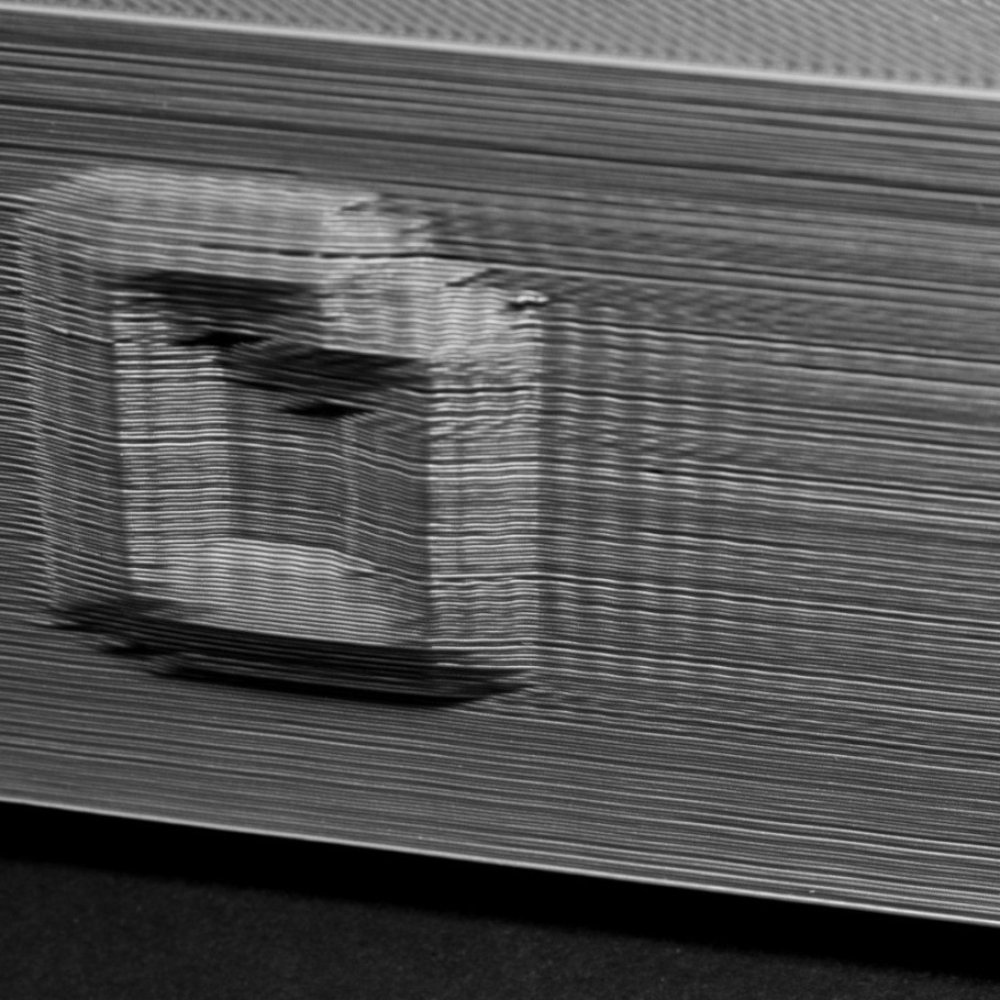
- Very long printing times: printing time can be shortened if jerk values are set correctly. The maximum speeds set in the G-code are reached faster and demand less distance.
- Excessive vibration: When the printer changes direction at angles close to 90 degrees, unwanted vibration occurs in the hotend. This vibration is transmitted to the piece, generating an “echo” on the outside of the piece. This problem, known as ghosting or ringing, depends (among other things, like belt tension) on the way the printer speeds up its moving parts.
- Weakening the structure of the 3d printer: This problem is seen more frequently in printers with a direct extrusion system since the extruder and the hotend move together. The accelerated mass leads to the structure of the printer constantly shaking, loosening nuts and bolts, and further increasing the original problem.
- Rounded corners: Sometimes the sharp corners of a piece come out rounded, due to improper jerk adjustment. It must be corrected for the hotend to correctly change direction.
Consequeneces of acceleration settings of printing quality
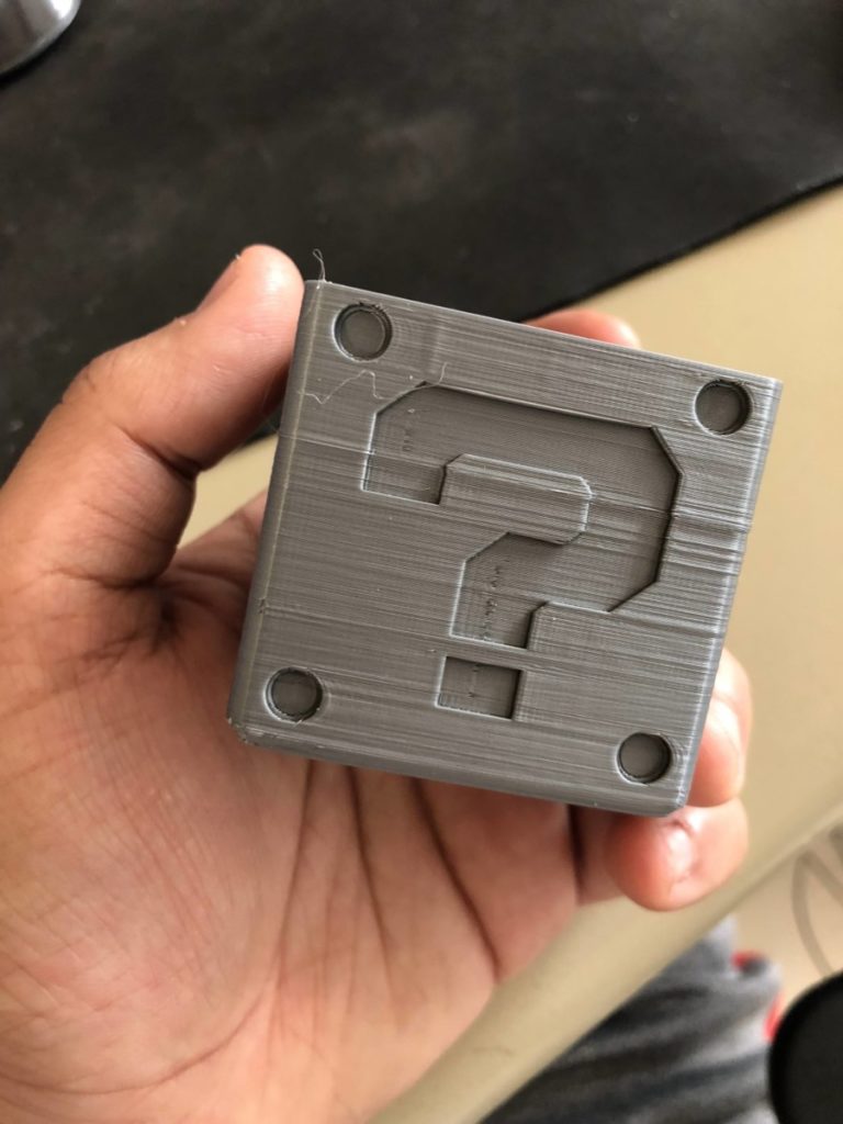
- Excessive noise: When the acceleration is too high, the printer produces very loud noises. A correct setting can help reduce the sound coming from the printer.
- Z-wobble: This problem manifests as a variation in the dimensions of the part along the Z-axis. If the vertical rods are not bent, it is very likely that the acceleration is too high.
- Layer line skips: If the hotend moves too fast before extruding, a small part of the line will be empty.
Finding the optimal Jerk and Acceleration settings
Optimal Jerk settings
Jerk values can be changed directly from the printer menu. In the Control command, select “motion”. There you will see the following values:
- Vx-jerk
- Vy-jerk
- Vz-jerk
- Ve-jerk
As the jerk value on the z-axis is normally inconsequential for printing, we will leave the previously set value. In the same way, it is recommended that you do not change the Jerk value of the extruder.
The movement in X and Y should be as similar as possible, so we will always use the same jerk value in both settings. Try changing this setting up to a maximum value of 20 mm/s.
The easiest way to find the correct jerk value is to make several identical prints modifying this value at 5 mm/s on each iteration.
Optimal Acceleration settings
Acceleration values can also be changed directly from the printer menu. In the Control command, select “motion”. There you will see the following values:
- A-travel
- Amax X
- Amax Y
- Amax Z
- Amax E
As with the Jerk, I recommend only modifying the acceleration on the X-axis and Y-axis only.
This time, the jumps on each test can be 100 units each. A commonly agreed and conservative starting point is at around 400m/s^2
The following calculator from Prusaprinters can be very useful to see on a graph how much distance the printer needs to reach the desired speed, with different acceleration values.
This other calculator allows you to know the maximum acceleration that your printer supports, knowing the mass of the moving load and other known parameters. It also lets you know if your current acceleration values make our printer unstable. Although it is interesting from an engineering and educational point of view, nothing beats iterating through several values until finding the sweet spot between printing speed and quality.
Some slicers like Cura, allow you to modify these settings by using g-code instructions. For example, the M205 command controls jerk. I recommend you to control jerk and acceleration from your 3d printer, and then save the best values in the EEPROM memory.
Using binary search to find the optimal Jerk and Acceleration
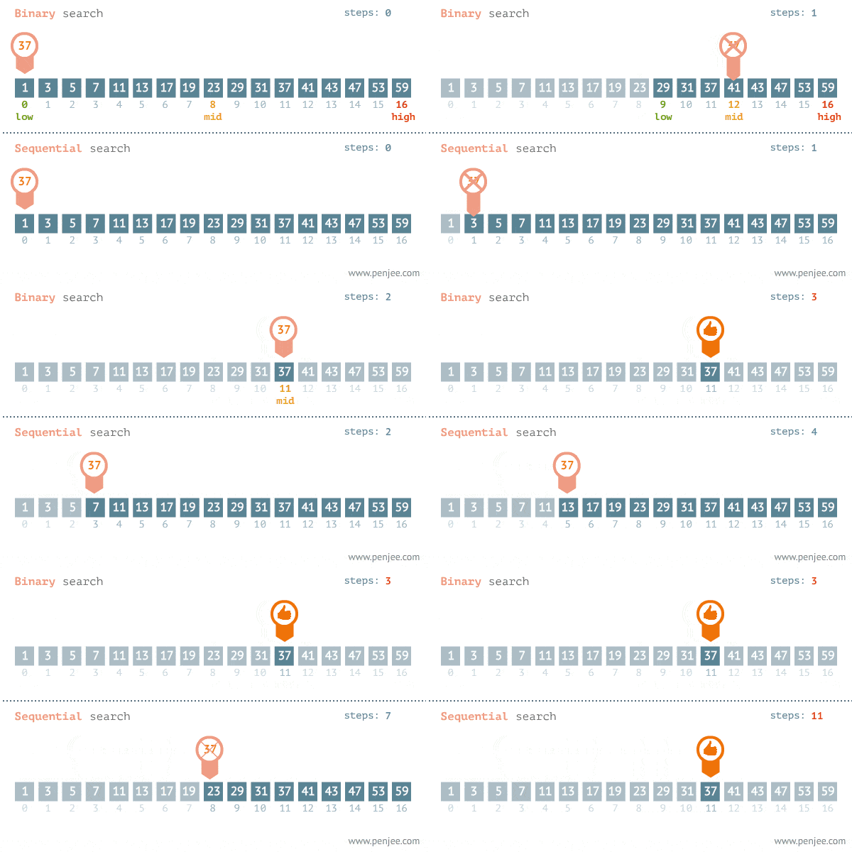
Binary search is a method commonly used in computer programs. It consists of establishing two values, a lower one (let’s call it A) and a higher one (let’s call it B). The average value (in order to not use our creative powers, let’s call it C) is calculated as half of its sum: (A + B) / 2 = C.
If we set the value C in our print parameter, and print a test object, we can check the result.
- If it is too high, the value C is exchanged for the value B, obtaining (A + C) / 2.
- If the value is too low, A is exchanged for C, obtaining (C + B) / 2.
Thus, it is not necessary to test by raising the value little by little in each print, since the interval is cut into 2 parts with each additional iteration.
This method can be used for tuning any other setting on your printer (like speed or temperature), so give it a try if you don’t know where to start.
Models to test Jerk and Acceleration settings
There are several models that allow you to check or calibrate the jerk and acceleration settings on your printer. Some of them are specific to these settings and many others give an overview of all the print parameters working together at the same time.
The best test to configure the acceleration can be found here (Thingiverse). It is fully customizable and consists of a single-wall-thick piece that varies the acceleration value as the print rises in the Z-axis. In the end, you can clearly see the acceleration values that generate vibrations in the piece.
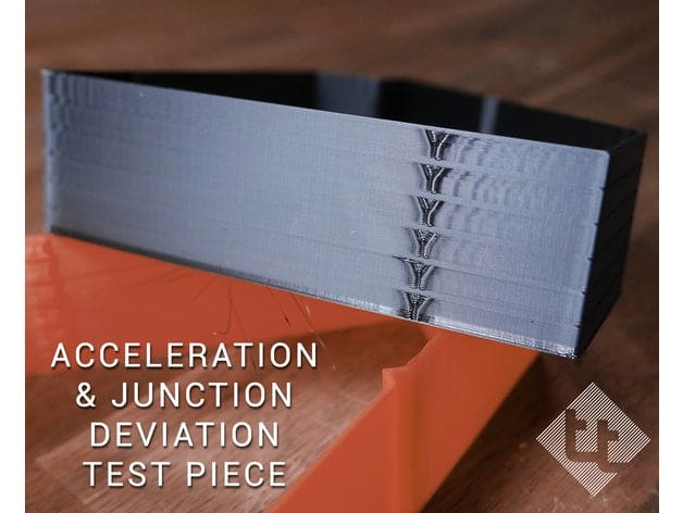
When testing for the optimal jerk settings, I find the following object very useful, as it exhibits many directional changes on a quick-to-print part. When printing you must ensure that the corners are correctly formed and that there are no vibration signs near them.
Last but not least, an object that tests all the printing parameters at once. Although it needs no introduction, Benchy highlights all the printer’s calibration problems. The surface on the exterior wall must be smooth, without traces of vibration. The corners of the roof should be perpendicular and end at a 90-degree angle. I recommend you to print Benchy after getting temperature and retractions properly calibrated, in order to get the best results.
Check out our recommended products section
We created a recommended products section that will allow you to remove the guesswork and reduce the time spent researching what printer, filament, or upgrades to get, since we know that this can be a very daunting task and which generally leads to a lot of confusion.
We have selected just a handful of 3D printers that we consider to be good for beginners as well as intermediates, and even experts, making the decision easier, and the filaments, as well as the upgrades listed, were all tested by us and carefully selected, so you know that whichever one you choose will work as intended.
Error processing API data.
